Transmitter :- Today We Will
Study and Learn about the 2 wire 3 wire and 4 Wire Transmitter Configuration
with Diagram.
Many Instrument Pressure, Flow , Level are Connected
to Different Method (2 Wire Configuration and 4 Wire Configuration.
A transmitter is an instrument that
converts the small signal from a sensor to a signal which represents the
variable being measured.
2 Wire Transmitter :- It is
possible to convey electrical power and communicate analog
information over the same two wires using 4 to 20 milliamps DC, if we design
the transmitter to be loop-powered. A loop-powered transmitter connects to
a process controller in the following manner:
Here, the transmitter is not really
a current source in the sense that a 4-wire
transmitter is. Instead, a 2-wire
transmitter’s circuitry is designed to act as a current regulator, limiting
current in the series loop to a value representing the process measurement,
while relying on a remote source of power to motivate the electric current.
Please note the direction of the arrow in the transmitter’s dependent current
source symbol, and how it relates to the voltage polarity marks. Refer back to
the illustration of a 4-wire transmitter circuit for comparison. The current
“source” in this loop powered transmitter actually behaves as an electrical
load , while the current source in the 4-wire transmitter functioned as a true
electrical source.
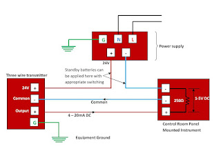
3 Wire Transmitter :-
Some Transmitters require more Power than the signal
Loop(4-20 MA) Can Supply their internal Circuit. A DC Common wire is run from the instrument
to the Transmitter . this Permits the transmitter to draw what ever power it
needs from the Power Supply and Produced
the Desired Signal Current Signal current at the transmitter output .
4 wire Transmitter :- The simplest form of 4-20 mA measurement
loop is one where the transmitter has two terminals for the 4-20 mA signal
wires to connect, and two more terminals where a power source connects. These
transmitters are called “4-wire” or self-powered. The current signal from the
transmitter connects to the process variable input terminals of the
controller to complete the loop:
A 120 VAC/240VAC Source is Connected
Only to the Receiving Instrument. These are often used where an Instrument is
Added to To the load of the DC supplies.
A Voltage Signal range of 1 to 5 Volt is
Standard although Some Model of Controllers use Different Voltage range and therefour
Require Different Precision resistor Values. If the Voltage Range is 1 -5 Volts
and the Current Value Range is 4-20 Ma. The Resister Value Should be 250 ohm.
Note :- This is Only Knowledge Purpose and Blog Contain is my View + Internet Search and Guideline


0 Comments